 Download area


A pneumatic brake is a key component in converting lines because it generates the controlled braking torque required to manage web tension during unwinding. When properly selected and integrated, it helps improve process stability, product quality and overall production efficiency.
What you’ll find in this article:
What is a pneumatic brake and what is it used for?
A pneumatic brake is a tension control device in which a compressed air circuit activates pistons and braking elements to generate a controlled braking torque on a rotating reel. In converting applications, its main role is to support a web tension control system during unwinding, keeping the process stable, accurate and repeatable even when reel diameter, line speed or process conditions change.
For this reason, a pneumatic brake does not simply slow down the unwinding axis. It works as an integral part of a web tension control system. Its job is to transfer the correct braking torque to the process so that the material always remains under the right working conditions.
Unlike pneumatic brakes used in other industries, such as automotive systems, industrial pneumatic brakes for converting must operate continuously on a reel, ensuring stable braking over time and a reliable response to process variations.
Why is it used in converting applications?
Controlling tension during the conversion of any material is essential to guarantee stability, precision and production continuity. Every material has its own physical characteristics and reacts differently depending on machine conditions. That is why web tension cannot be left uncontrolled.
A pneumatic brake is used because it makes it possible to generate and regulate the braking torque needed to keep the material under control during unwinding. If braking is not correct, web tension becomes unstable and the entire process is affected.
Effective tension control helps prevent material instability, wrinkles, stretching, winding defects and, more generally, reduces production waste and machine downtime.
When tension remains stable and reliable, the material behaves more predictably throughout the line. This leads to better process quality, more accurate converting operations and higher plant efficiency.
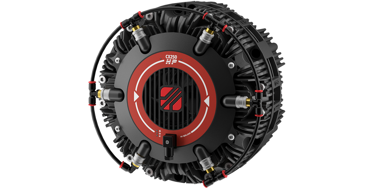
Main components of a pneumatic brake
A pneumatic brake is made up of several elements that work together to generate the braking torque required for tension control.
- Compressed air circuit: This activates the braking system and can be managed manually or automatically through a tension control system.
- Pistons: These are activated by compressed air pressure and convert pneumatic energy into a mechanical force that pushes the friction pads against the disc.
- Friction pads: Made of friction material, they are pushed by the pistons against the braking surfaces of the disc to generate torque.
- Disc: Connected to the unwind shaft, it is slowed down by the friction generated by the pads.
- Ventilation: To improve heat dissipation, the brake may be equipped with an internal or external fan, depending on the configuration.
- Brake structure: The brake housing or supporting structure must be designed to ensure mechanical strength and maximize heat exchange.

How does a pneumatic brake work?
A pneumatic brake operates when the compressed air circuit is activated. Air pressure acts on the front surface of the piston and generates a force proportional to the pressure itself.
This force pushes the pads, which are linked to the pistons, into contact with the braking surfaces of the disc. The friction material of the pads is designed to provide a suitable friction coefficient to generate the braking torque required by the process.
The operating principle can be summarized as follows:
pneumatic pressure → clamping force → friction on the disc → braking torque
By modulating pneumatic pressure, it is possible to regulate braking torque and therefore influence the tension of the material being processed.
Fp (piston force) = P [bar] x Ap [mm2] = [N]
Ft (tangential force) = Fp [N] x µd = [N]
C (braking torque) = Ft [N] x b [m] = [Nm]
P = Pressure | Ap = Piston area | µd = Dinamic friction coefficien | b = lever arm (distance piston thrust center/brake axis)
In automatic tension control systems, for example those based on load cells and tension controllers, braking torque is managed dynamically according to line conditions. In this way, the system can adapt to variations in reel diameter, speed or material, maintaining web tension as stable and optimal as possible.
Main features for choosing the correct pneumatic brake
For a pneumatic brake to work effectively in a converting line, several key features must be evaluated carefully. The quality of tension control depends not only on the braking principle itself, but also on how accurately and consistently the brake can generate and maintain the required torque.
Torque stability and linearity: The brake must deliver stable and linear torque over time. Internal mechanical friction or poorly optimized design solutions can generate torque fluctuations and therefore less accurate tension control.
Heat dissipation: During continuous operation, the brake converts energy into heat. Efficient heat dissipation is essential for maintaining constant performance and, in many cases, makes it possible to use more compact solutions even in applications with high power dissipation.
Adaptability to the required torque: The same production line may process different materials and operate under different working conditions. The brake must therefore be able to adapt to the torque required in each situation.
Long-term reliability: In converting, pneumatic brakes often operate continuously. To ensure consistent performance over time, all components must be designed to resist wear and maintain the required behavior even after many hours of operation.
Ease of integration: It is also important to evaluate how easily the brake can be integrated into an existing unwinder or a new machine. Dimensions, mounting configuration and compatibility with the control system all directly affect machine design.
Maintenance: Because this is a braking system subject to continuous operation, maintenance is a key factor. It is therefore advisable to choose brakes that offer long component life and simple, fast servicing.
Robustness: Given the working loads, industrial environments and reel masses involved, pneumatic brakes must be robust and resistant, even in the presence of shocks or demanding operating conditions.
Which braking systems are used in industrial applications?
Several braking technologies are used in industry, each with specific characteristics and fields of application.
- Electromagnetic brakes: These are often used in applications with low torque and limited dissipation, or in environments where dust emissions are not allowed.
- Hydraulic brakes: These systems are more complex in terms of management and maintenance and are now far less common in converting.
- Eddy current brakes: Also known as Foucault current brakes, they generate braking force without physical contact by exploiting magnetic fields and induced currents. They are special solutions used in specific applications.
- Manual belt systems: These are now largely outdated in modern converting, where higher precision, stability and automation are required.
In this context, the pneumatic brake remains one of the most widely used and reliable solutions for unwind tension control.
Where is a pneumatic brake used and what are its advantages?
A pneumatic brake is used in all applications where a reel of material must be unwound in a controlled way.
More specifically, it is commonly installed on the unwinders of:
- printing machines
- flexible packaging lines
- label printing machines
- paper converting lines
- corrugators for corrugated board production
- slitter rewinders
- coating and laminating lines
- many other reel-to-reel production systems
In all of these machines, the benefits of a pneumatic brake are very concrete:
- more stable web tension
- improved final product quality
- reduced waste
- the possibility of increasing line speed
- greater production continuity and fewer unplanned stops
In other words, a properly sized and properly integrated pneumatic brake directly contributes to the overall efficiency of the plant.
Re solutions for pneumatic brakes
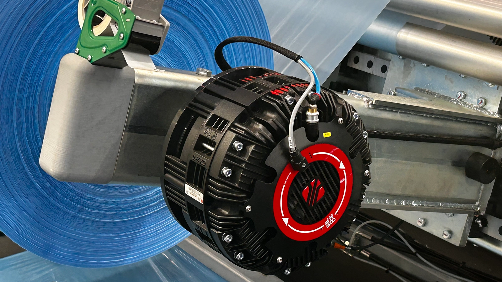
Since 1974, Re has been developing monodisc pneumatic brakes designed for converting applications, with a strong focus on torque stability, heat dissipation and continuous-duty performance.
Within the Re range, Combiflex pneumatic brake, introduced in 1980, has become a benchmark in the industry and is used by major OEMs worldwide.
It is a practical example of a pneumatic brake developed to meet the tension control requirements of material converting lines. Its success is based on the modularity of the system and the availability of different configurations, which make it possible to adapt the brake to a wide range of application needs.
Outstanding torque and dissipation performance, environmental respect, a wide product range and mechanical strength are just some of the characteristics that have made Combiflex a market-leading pneumatic brake solution.
F.A.Q.
A pneumatic brake is used to generate controlled braking torque during the unwinding of material from a reel. Its main role is to support web tension control and process stability.
It works through a compressed air circuit that activates the pistons of the braking system. The pistons push the pads against the disc and generate, through friction, the braking torque required by the process.
Because the braking torque generated by the brake directly influences web tension during unwinding. Stable braking helps maintain more consistent tension and a more precise process.
It should provide stable and linear torque, efficient heat dissipation, long-term reliability, adaptability to different operating conditions, ease of integration and simple maintenance.
It is mainly used on the unwinders of printing machines, flexible packaging lines, label lines, paper converting machines, corrugators, slitter rewinders, laminators and other reel-to-reel systems.